Eye Pattern Testing of high data-rate military slip ring assemblies

Some defence applications, such as gimballed optical systems, are using increasingly high data rates, for example 12G SDI. The Eye Pattern Test is a method for evaluating the ability of a network medium to transmit high speed data reliably. While it is preferrable to test the complete network, end-to-end, there is value in testing individual network components, such as the slip ring assembly.
The medium, in Pandect’s case a slip ring data channel, has a representative data signal transmitted through it and the signal at the receiving end is correctly terminated by a matched impedance and monitored with an oscilloscope that is sufficiently fast. The oscilloscope needs to have a sample rate of no less than 5 x the data rate of the signal being interrogated. i.e., for 12G SDI signals the oscilloscope needs to be capable of at least 60 GHz.
The data will be distorted by the transmission medium but if the signal can be reliably identified as low or high level the data will be valid.
In most systems the data is sampled only in the centre of the bit period which means that the rise and fall times are not so critical. The data format will specify the parameters such as the high and low logic thresholds, timing accuracy, rise and fall times.
For ease of explanation assume the data is a square wave.
The Oscilloscope will display the square wave but is set to trigger from both positive and negative transitions of the data so a trace will show a positive going pulse of the waveform and the following trace will show a negative (or inverted) pulse of the wave.
The Oscilloscope is set to infinite persistence so the display will show both positive and negative at the same time and collect many traces over a period.
For a good square wave this forms a shape which looks like two horizontal lines with vertical lines between them. As the data becomes distorted the edges of the data slow down and are no longer vertical, this forms a shape which looks like an Eye.
It is the area inside the Eye that is important.
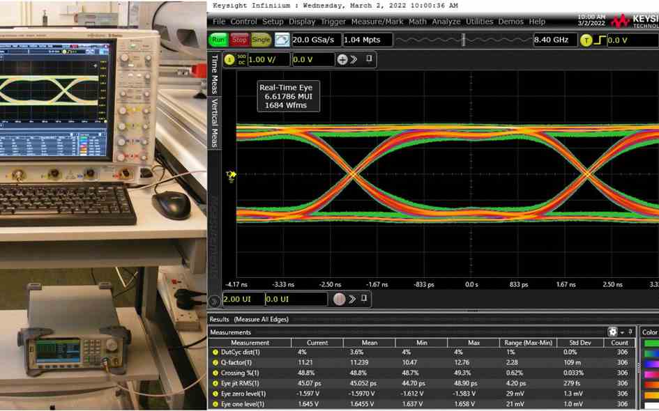
An actual Eye pattern test will use a PRBS (pseudo random bit sequence) and an Oscilloscope with an Eye pattern function. The Oscilloscope will synchronise to the data clock and accumulate trace data over very many bit periods and overlay the data on a single display, the display will be colour coded to show the statistical frequency (how often the data hits a particular point) of the data so that the trend can be seen.
This is a good visual way of representing the characteristics of the data transmission medium and the Oscilloscope may also measure the parameters specified for the type of data transmission to determine the performance of the slipring channel.
A trend can be seen, and it can be determined if the data fails to meet the specification at any time and if so, how often.
In the example shown here, we were testing the transmission of a 250 Mb/sec signal though a Pandect custom-designed slip ring assembly for a defence customer using a 4-channel 8 GHz oscilloscope.
More news
Questions? We'll put you on the right path.
Contact Pandect
or call
Pandect Precision Components Ltd
+44(0)1494 526 303/4
Want to find out more about Pandect?